Build this Joystick!
Now available:
Sheet metal parts
Here is a joystick based on accelerometers. The Principe used is to use the earth gravity field to monitor the position of the hand controls. To cancel out the effect of tilting the whole box a third accelerometer is attached to the box. The signal from this is subtracted from the accelerometers attached to the controls.
Data is gathered by the use of two 8 channel ad converters. The process is controlled with means of the Parallax propeller microprocessor.
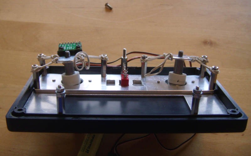
Here is the top panel seen from below. One of the accelerometers is mounted (to the left). In the middle is seen a switch for power off and on. The control sticks are hinged on ball joints. The slightly thicker plate is used both as a fix for the joints and a boundary for the movement of the sticks. The size of the round hole and the size of the white collar will set the maximum angular movement.
Rubber bands are used to position the sticks to neutral. They are held by 3 + 3 columns as seen. The last rubber band is attached to a plate seen in next picture.
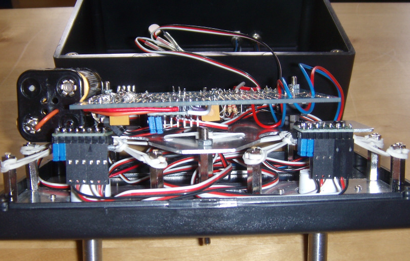
Hopefully there can been seen that both accelerometers are mounted. The parallax card with the microprocessor is mounted on a plate at some distance from the top panel. The last rubber bands are attached to this plate (somewhat shadowed). The static accelerometer will be found in the center of the picture. The battery is to the left. Only three batteries are mounted in the holder as 4.5 volts will be enough for driving. The orange wire leads the power through the empty space left by the missing battery.
Circuit scheme.
The scheme will be found here.
PCB layout. The placement of components will be found here.
Important note: The accelerometers sketched shall all be placed in the same direction physically (with controls in neutral). The scheme just indicates the circuitry, not the physical placement.
The scheme was drawn using the scheme for the parallax propeller proto board as a base. This scheme has been cut down why some of the wires are going into blind. Donít mind about that- they are simply not needed. Do also download the proto board scheme from the parallax home page (found in a PDF describing the proto board)!
The led is not actually needed. It indicates that things are running. It can be excluded after running up.
Code:
The code in text format will be found here. JoystX2_sandafp.txt
One of the objects in the code is Sandadata. It is found here Sandadata.txt
Other objects are found on Parallax homepage or in the software coming with the propeller. The only exception is the BS2_functions_fast object. It is the same as BS2_functions but with the only change that the waitcnt in the shiftin and shiftout PUB:s are changed to 500 instead of 1000. Thatís why its called "fast". You may use the original BS2 object but the code will be slower. On the other hand this change may affect the saturation of the ad-conversion. This could produce slightly less accurate values. However I think this is of low importance as about the same fault will go into every value so that after computing the angles (see below) the fault will be cancelled out.
As usual the code is in the spin language.
It mainly consists of gathering data from the ad-converters. 9 channels are needed so there is need for two ad:s. So there is actually 7 channels left. You may find some way to use them if you wish so.
After that data are filtered by simply making mean values. Here 10 consecutive data is used. This could be higher producing slower but more soft response.
Arc tangents are then computed for x and y directions with respect to z. This is a measure of the inclination of each accelerometer. The same computation is made for all three accelerometers. The value from the box-fixed accelerometer is subtracted from the other values. The result will be the angle of each control arm.
The result can then be used to steer a motor, motors or other things of your choice. In this case I have used pin 16 as output channel. In the scheme it is also protected by a 2.2kohm resistor. I have also indicated an input channel at pin 17. It is not used.
There is a debug part in the code. The object is cancelled out but can be activated by simply taking away the Ď characters in the beginning of the three rows
' debug.start(9600) ' start terminal, will by default (see obj debug) use pins 30 and 31
'debug.str(string(FF, "Joyst Channel Debug med 9600 baud", CR, LF, LF))
'debug.crlf
Do also change the 5 figure in "IF boink2 == 5" to 4 later down. After that the code will send debug information on the readings to a PC terminal window. This is useful for adjusting the tare when reading from the ad:s. For example
accx:= (accx-zero - 190)*-1
accy:= (accy-zero + 45)*-1
accz:= (accz-zero)*1
where the figures 190 and 45 are adjustments made to get a zero reading when the box is horizontal. The tare will differ depending on variations in make of the accelerometers and differences in the ad:s. There is also the effect coming from accelerometer not mounted exactly parallel to card.
Bill of materials
|
Item |
Make |
Info |
Designation |
Amount |
Ca price |
|
Box |
Hammond HD |
107X167X65mm |
1594EBK |
1 |
13$ |
|
Accelerometer |
Polulo/Memsic |
Break out board |
MMA7260QT |
3 |
13$ |
|
AD-converter |
Microchip |
8 channel |
MCP3208-CI/P |
2 |
6.50$ |
|
Protoboard |
Parallax |
32212 |
1 |
25$ |
|
|
Extension cable |
Parallax |
3 part |
805-00012 |
6 |
3$ |
|
Resistor |
10k |
2 |
|||
|
Resistor |
2.2k |
2 |
|||
|
Resistor |
180 Ohm |
1 |
|||
|
LED |
Typical 10-30mA |
1 |
1$ |
||
|
Capacitor |
0.1uF |
2 |
0.50$ |
||
|
Wire |
|||||
|
Battery holder |
1.50$ |
||||
|
Ball joint |
SKF |
22mm |
GEH 10 C |
2 |
27$ |
This is totally about 160$. Out of this prize the two ball joints represents more than 50$. I think this can be reduced. Look around and you may find something else with the same function, alternative supplier could be Nomo for example ore maybe some surplus material from other area (car stock, mc etc). You also need some material for the sticks.
Control sticks: Here is a drawing of the sticks. Click on picture to find details.
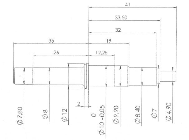
Axle. Details here.
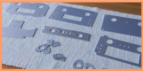
The box is very nice being a heavy duty type so it has nice thick walls. But it actually is a little to small. You have to be very careful to get everything into it. So a somewhat bigger box would be beautiful. The best had been the same type of box but bigger. However this is the biggest model of that type. I have made a sheet metal kit that will fit in the box. Of course the kit can also be used for a bigger box.
The device has now been tested with the submarine in a lake. It performs pretty well and gives good control of the submarine.
Pimped version.
If you want you can ad on switches and display. I used small Taiway switches. The display is the parallax serial LCD (#27979). As can be seen from the second picture from top (inside of the top cover). There is a cut out in the plate. This is for the display. There is a small drawback of using their display. It requires 5 volts so my construction with only three batteries is not sufficient. I solved this problem by adding four more batteries. I also split the parallax proto board at the 5 volt regulator. This makes it possible to have separate power sources to display and control circuitry. The fine thing being that the display can be turned off without the control turned off. The display takes a lot of power, especially when lit so it can be nice to have it turned on only when needed. The result look like this:
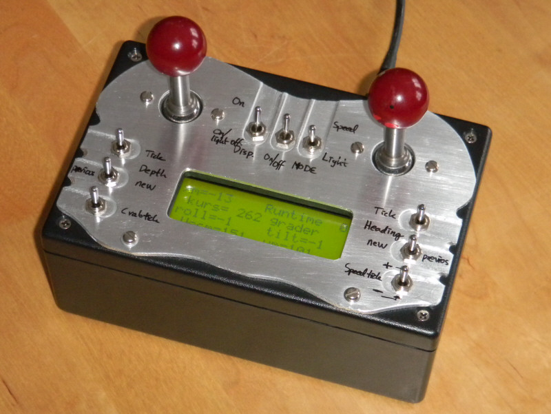
I have used a 2 mm aluminum plate on top. It has an "organic" shape. The display shows read back of data from the ROV. This gives the opportunity to steer the vehicle with respect to for example measured heading.
So keep on experimenting.
I which You good luck building this joystick!
Jacob
(((Back to main page)))