Build this Joystick! Mechanical description.
Now available:
Start.
To start with you need some tools. They are not so many and you probably already have some of them or could borrow from a friend. For an easier work the tools should be sharp, for example drills and knife.
So here is a list of what is needed:
Drills: 2,5 or 3mm and a 6 or 6,2mm drill. In inch that would be one 1/8" drill and one ¼" drill. ¼" is a little more than 6,2mm but that would do.
Drilling machine, either motorized or hand driven.
A tap for threading. Thread M3 or close to this dimension Inch type thread that will fit your choise of screws with inch dimension.
A counter sinking device
Nice thing to have but not a must: a step drill ranging from about 6mm to at least 22mm.
A good file medium sized with one rounded and one flat side, medium fine cut.
A round file, diameter about 5mm and relatively fine cut.
A good knife.
A nice chisel. The need for this is somewhat optional. It’s used to make space for one of the battery holders in a nice place as seen in a picture lower down in the description. This placement is however not urgently needed and therefor the joystick could be built without the chisel.
An electricians pliers (cable cutter). Fresh with sharp edges.
A sharp tool for marking.
Something to measure with.
A pencil.
So shall we go?
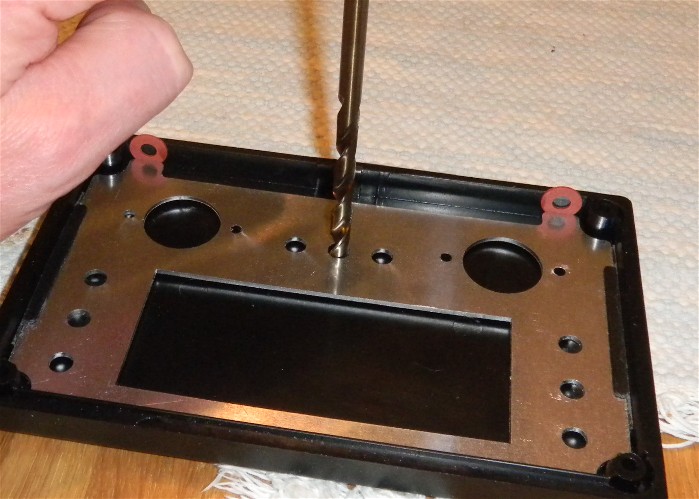
Place the "under plate" inside the lid. Use small washers to locate it towards the lower end as seen in picture. To make it center in left right position pieces of plastic or more washers can be used. Also several layers of tape would do. Do also place something between the lid and the plate so that a space of about 1-2 mm is left. The space will make the drill center more easily. Take a drill 6 or 6,2mm wide. A ¼" drill would also do but then you have to cut somewhat into the plate also. Drill the nine holes using the sheet metal plate as a guide.
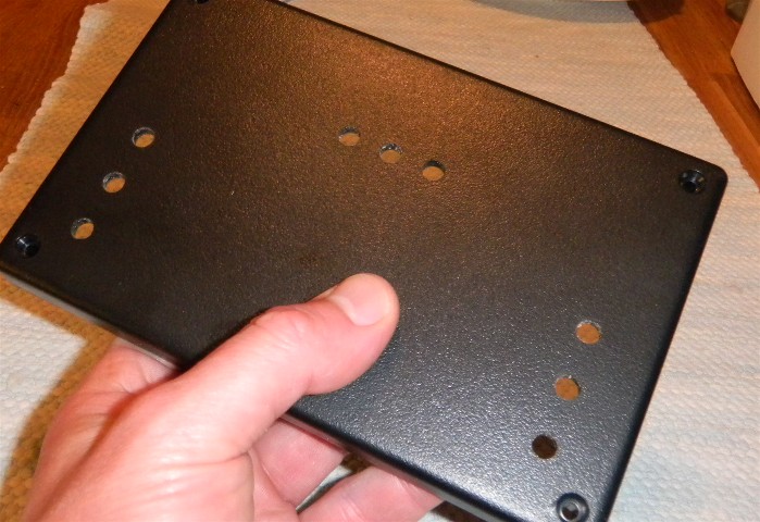
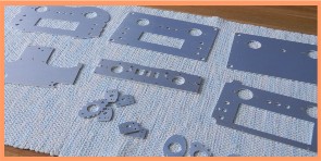
Result.
Assemble the under plate, the lid and the top plate by of some of the switches.
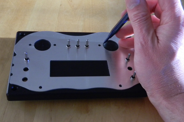
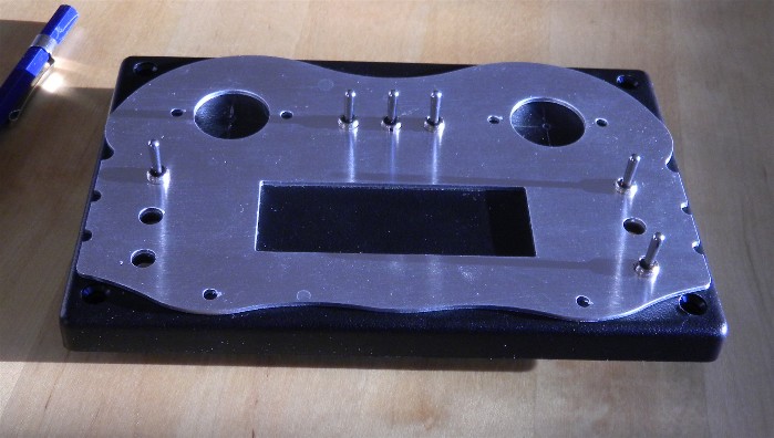
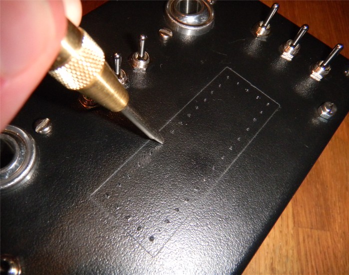
Use a sharp tool to mark out the edge of all big holes, both round and square.
Mark out the center of the circles made at the ball joint positions. Try to be careful as the final result will be dependent on this.
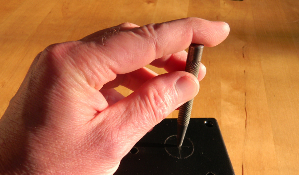
Make a good center mark.
Open up the two holes. You can drill several holes just inside the circle mark using the 6mm drill. Then cut through by the pliers and then grind the hole to the right dimension. Use the ball joint as a gauge. Or you could use a step drill to perform the operation. This is very comfortable but a step drill will cost you some money.
Use a pair of pliers to take away some material at the inner corner of the lid. Affected are both corners close to the ball joint positions. Material should be taken away from the round protrusion where the screw pass. Do only take away material as shown in picture, not breaking through the passage for the screw.
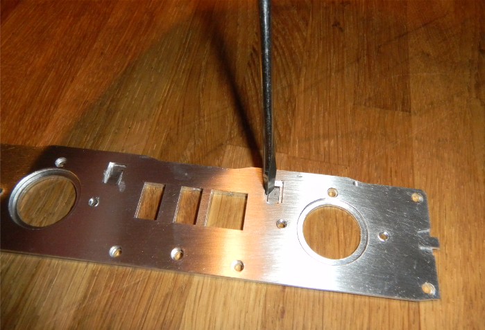
The column plate comprise two parts. One upper and one lower. The upper have four tongues that should be bent down into holes precut in the lower part. Use a screw driver as shown to start the bending. Then use a pair of pliers as shown in the next picture. When starting bending do this in steps to ensure that the plates are aligned and that all tongues will go down into their corresponding hole.
Bend the tongue with a pair of pliers. Be careful to bend either side a little at once to be sure that the both plates fully align to each other. Do continue until the tongue is bent almost 180 deg.
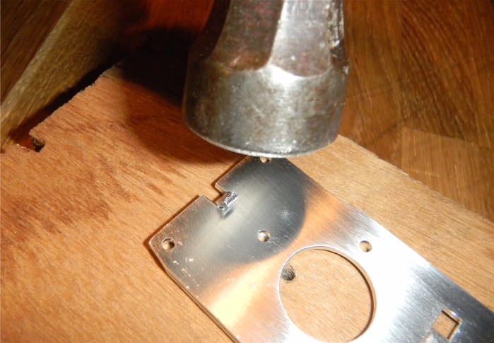
Use a hammer to rivet the bent tongue down a little. Be gentle.
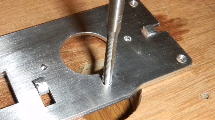
Make threads. M3 ore if you choose: an inch thread with a diameter close to 3mm. You can see two of the riveted tongues in picture.

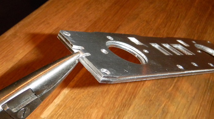
This adjustment is made to be nice to the ribbon cables connected to the moving accelerometers not to wear them down. The grinding do not have to be very large. But can be made slightly oblige so that the angle between the face in picture and the ground down edge will be somewhat blunt. Do smooth all of the edge not only ground areas. Do also make a light chamfer at the big holes. You can adjust the maximum movement of the control sticks by making this chamfer bigger.
Make marks in the display window area with a sharp tool. Make the marks with some distance to the marked outline. After drilling there should be some material left to grind away.
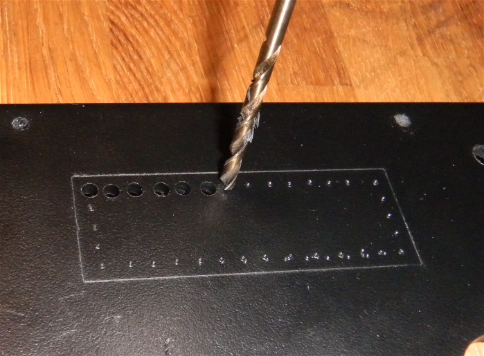
Drilling. Good advice: first drill with a diameter that result in holes not falling into each other. After that, drill with a diameter resulting in holes almost protruding the wall of its neighbor.
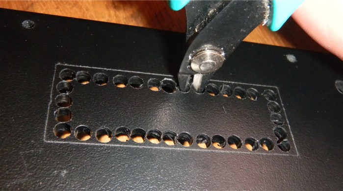
Finally use a pair of pliers to cut through the small walls.
Then use a file to trim the opening almost up to the markings. Leave a little so that the hole is slightly smaller than the hole in the top plate. 0,3mm is enough.
When mounting a display window (transparent plastic) this will rest on the small cat walk left.
Bring the card plate.
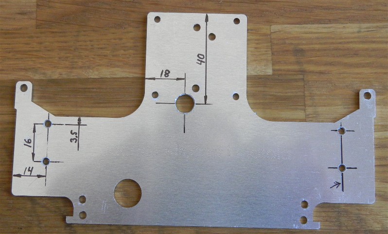
Make five more holes in the plate. The holes are not needed if you are up to build the simple version. Four 3 to 3,5mm (1/8") holes. These are for holding two battery holders for the display drive. One hole about 8mm diameter. This hole can be useful if you would need to access the small switch on the backside of the display. Place the holes as indicated in the picture. Measures are in mm.
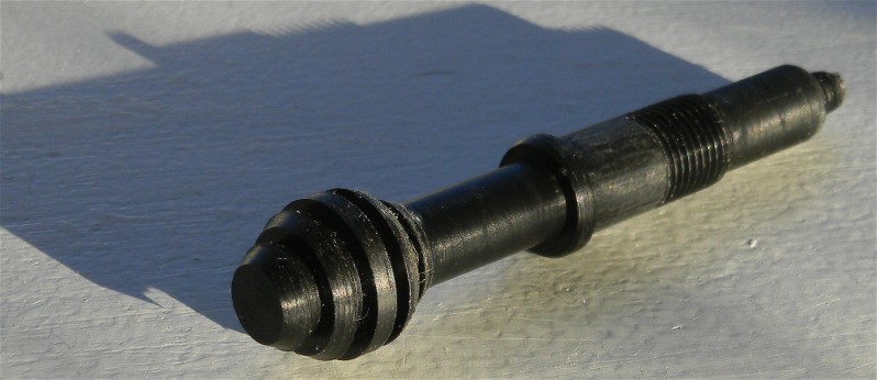

Here is shown lever of plastic type. Drawing of the axle can be found at bottom of this document. In lower picture equipped with ball joint, collar, accelerometer plate and a small nut (M5).
Start to assemble
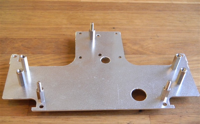
Mount spacer bolts in the card plate. Four 15mm bolts for the battery holders. (Not needed for simple version). They should be mounted with male threaded side down to the plate. Three 12mm bolts to hold the card. With threaded male side upwards.
Bring the lid.
Place the under plate inside the lid. Do also place your choice of top plate on top side. Fix all together with two Taiway switches as indicated.
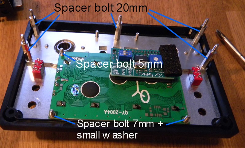
Use tapered screws to mount 5 20mm spacer bolts to the column plate. The tapered screw heads should not protrude over the column plate surface. Do also mount two 5mm spacer bolts as indicated in the same manner (one is hidden).
Drop the ball joints in. If properly made the joints should slide in pretty easily. Otherwise you have to adjust the lid a little. Place the column plate and fix it with four screws (M3 or suitable inch screw) at ball joint lock plate positions. Do also mount lock plates at the same time.
Now mount two 7mm spacer bolts as indicated with screws protruding from top side of lid. Place a small, thin washer on each 7mm spacer bolt. Then mount the Parallax text display as indicated. You can check that the glass of the display comes very close to the lid. The distance should be zero or one or two tenth of a millimeter.
Note the small switch on the parallax display. The position of the switches should be adjusted as indicated in the programming section.
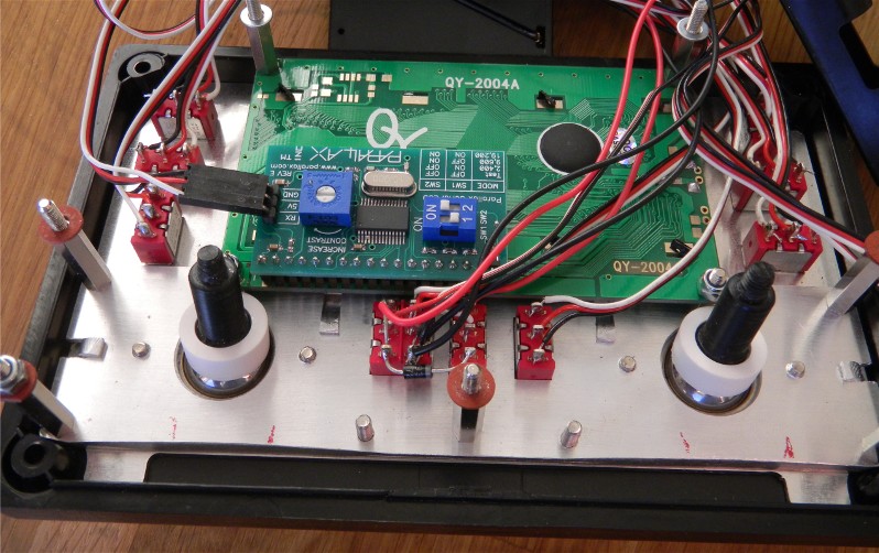
Protrude levers from upper side and lock them with the white collar nuts. In the picture is also seen wiring and switches. This is the time when the connecting points of the switches are most accessible. But you may assemble the whole construction first and then disassemble to this point and perform the soldering. For placement of wiring refer to the electrical section. In picture is clearable visible the correct positions of the switch on the display for 9600 baud transmission rate. Do also note that the three point connector on the display were bent about 90 deg. (Be careful).
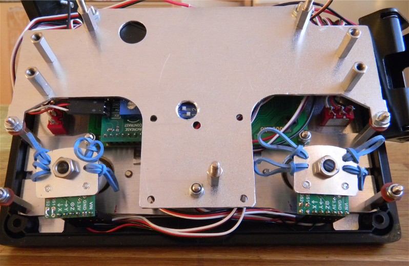
Now mount the card plate ready with pre-mount distance bolts. Don’t forget washers as seen in former picture. Two thin steel washers and three somewhat thicker fiber washers. Mount accelerometer plates with accelerometers on. How to is described in the electric’s section. Also here is shown wiring but you can wait and install them later.
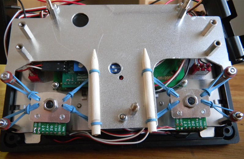
Mount rubber bands. Helpful can be to make a hook out of a piece of jumper wire to pull rubber band through hole. Flower sticks are used as anchors. By grinding groves in the small pieces of wood the tension of rubber bands can be adjusted. This way position of levers can be adjusted. (Not all rubber bands have the same properties).
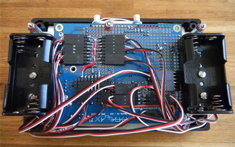
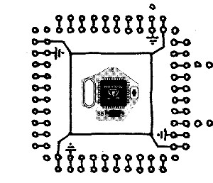
Now mount the parallax proto board, on top of the three 12mm bolts. First place fiber washers on the bolts to enhance the distance a little. In the picture is also seen battery holders and some wiring. Note the battery holder in center: Next point describe how to do it.
Tricky point.
One of the battery holders is hard to get into place, there is not space enough in the most preferable position.
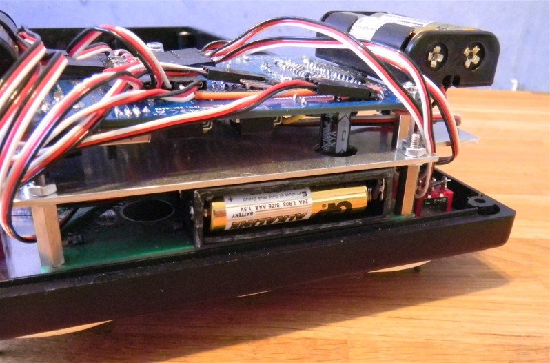
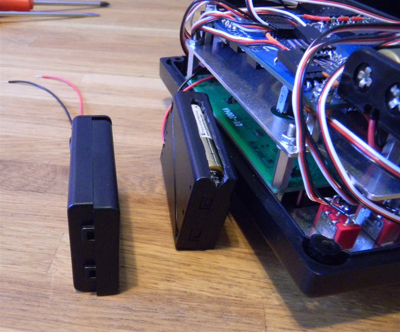
A good position for this battery holder is immediately adjacent to the display PCB (between the PCB and the plate)
In picture the holder have been cut down to make mounting possible.
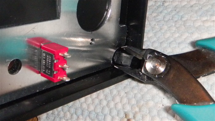
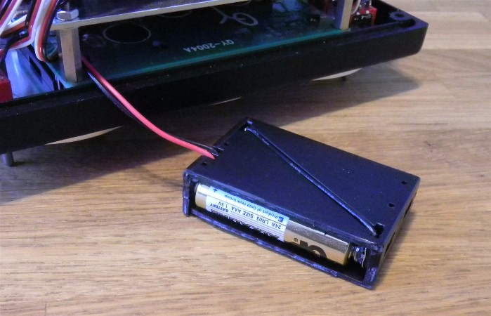
Here can be seen one unaffected holder and one cut. Below is presented some pictures to show how to cut down the holder.
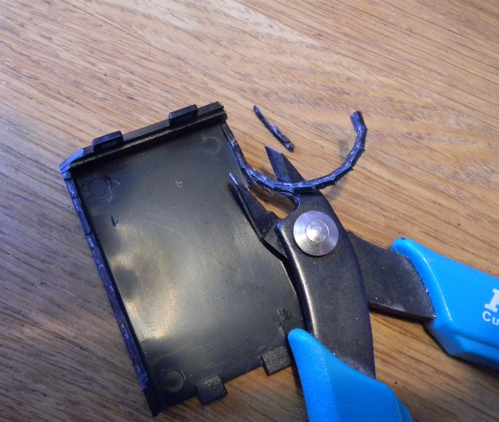
Use a pair of pliers. Here is the lid cut down. Note that one side wall is completely cut away while the other one (here to the left) is only partly cut away.
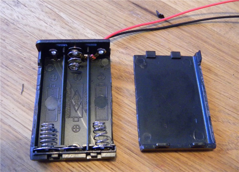
Cut completed on both top and bottom part.
Now this is not enough. There have to be some work done on the box to.
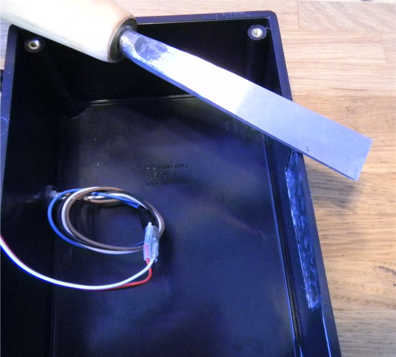
The region close to the position of the holder is cut down by means of a chisel. About 1mm of the original 3.5mm thick wall have to be taken away.
Alternative: If you don’t want to do this the battery holder can be placed simply at the box floor swimming around among the wires situated here. There are a bunch of wires so it will be trapped in a soft net. The disadvantage is that lifting the lid of the box; the holder will be dangling around without support. With the former method the lid will present a stand alone system, all parts fixed.
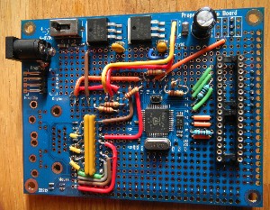
Mount battery holders for display drive. Use tapered screws. In picture are also seen full wiring harness (interface wire missing). Check electric’s section scheme. Mount batteries.
Load program (se programming section).
Turn power on.
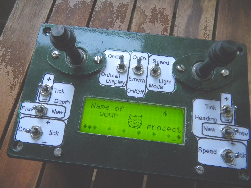
The display should light up and show your project name.
Control sticks: Here is a drawing of the sticks. Click on picture to find details.
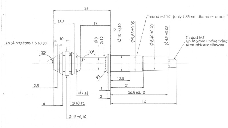
If you have problems to produce the axle yourself I have the possibility to provide a pair for you. Ask for price and details.
Electric description Function and code